
 Reply With Quote
Wow very cool


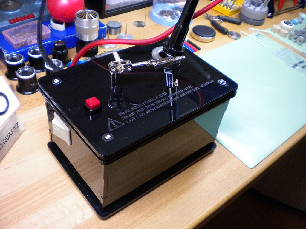
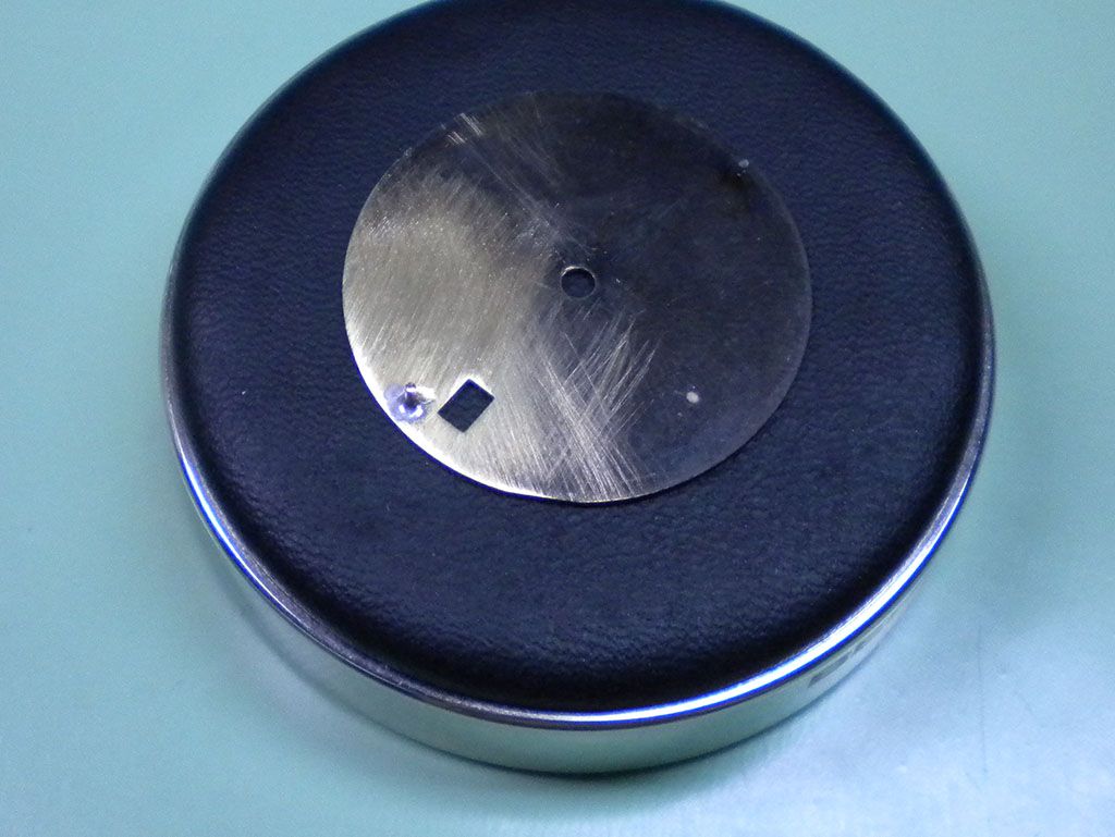
I took delivery of a new bit of kit yesterday, and managed to have a bit of practice with it today. The machine in question is a dial foot solderer
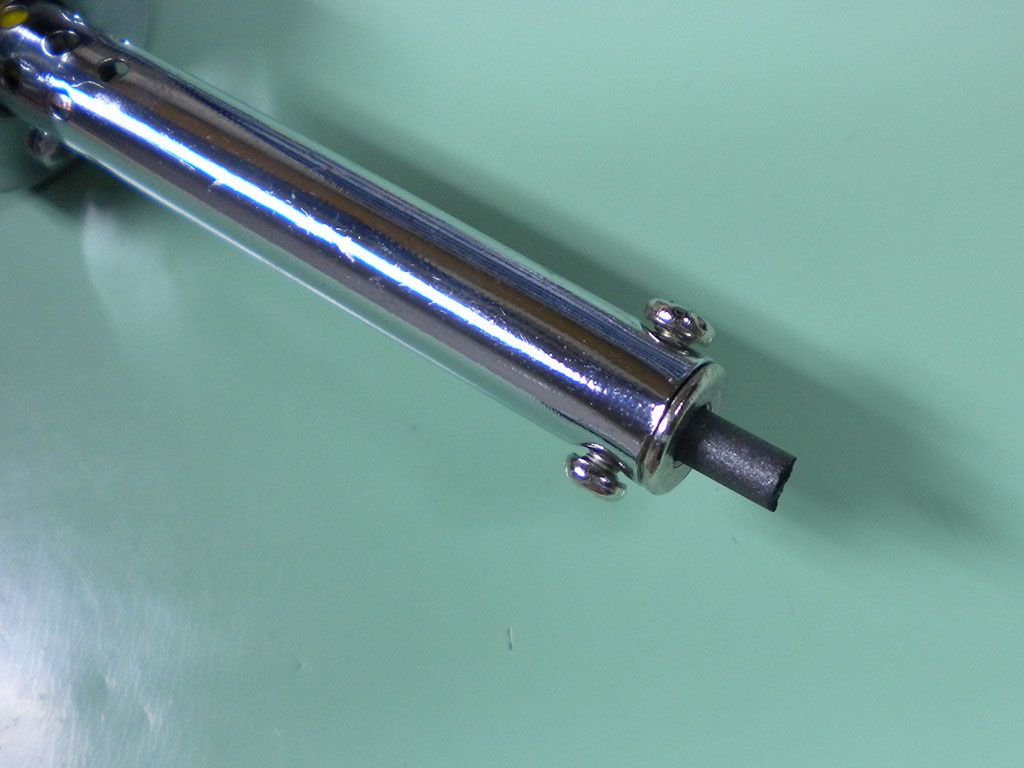
It has a clamp to hold the dial, another to hold the copper wire which goes to make the new foot, an on off switch, a power button and a "soldering iron" that has a carbon rod in place of a tip.
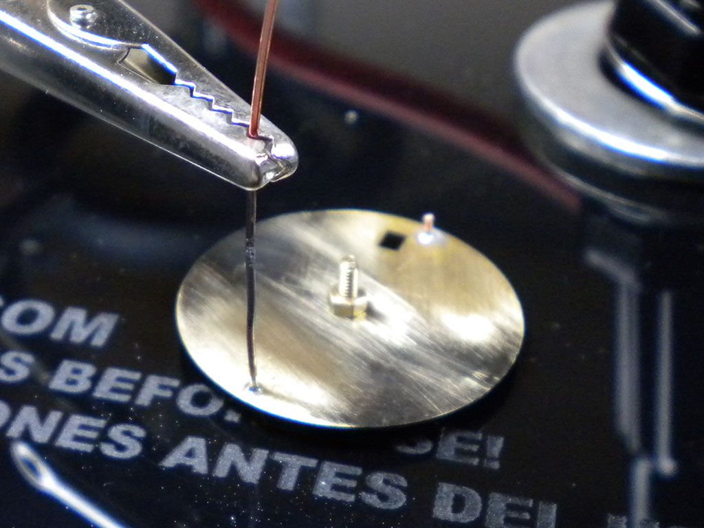
The idea is clean the dial down to the brass and mark the foot position, clamp it on the earth post, clamp the wire in place with the adjustable crocodile clip, apply a dab of flux, place some pieces of solder around the joint, touch the carbon rod onto the wire and press the button until the solder flows.
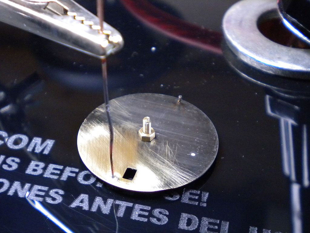
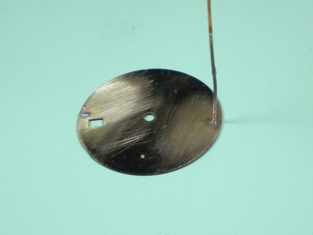
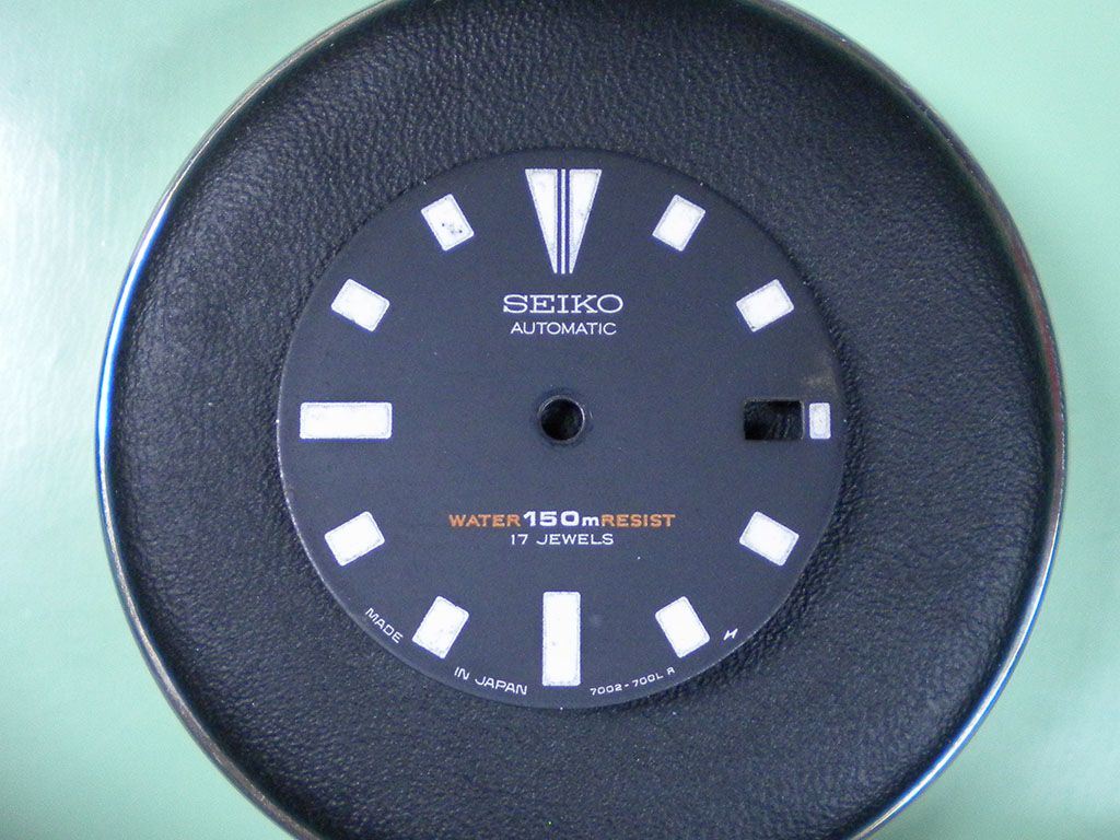
I found an old dial with one foot missing and the other folded flat against the dial to have a practice with. I did the all the above and the result was as below.
It took me three attempts to get a good joint, I found that filing the wire flat where I'd cut it and placing the tiniest chunks of solder around the periphery of the joint was the best method and gave the strongest joint.
The excess wire is cut and the end filed flat.
I snapped the other foot off as it was almost split right the way through and had another go.
Another strong joint
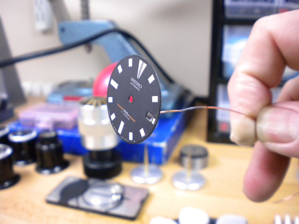
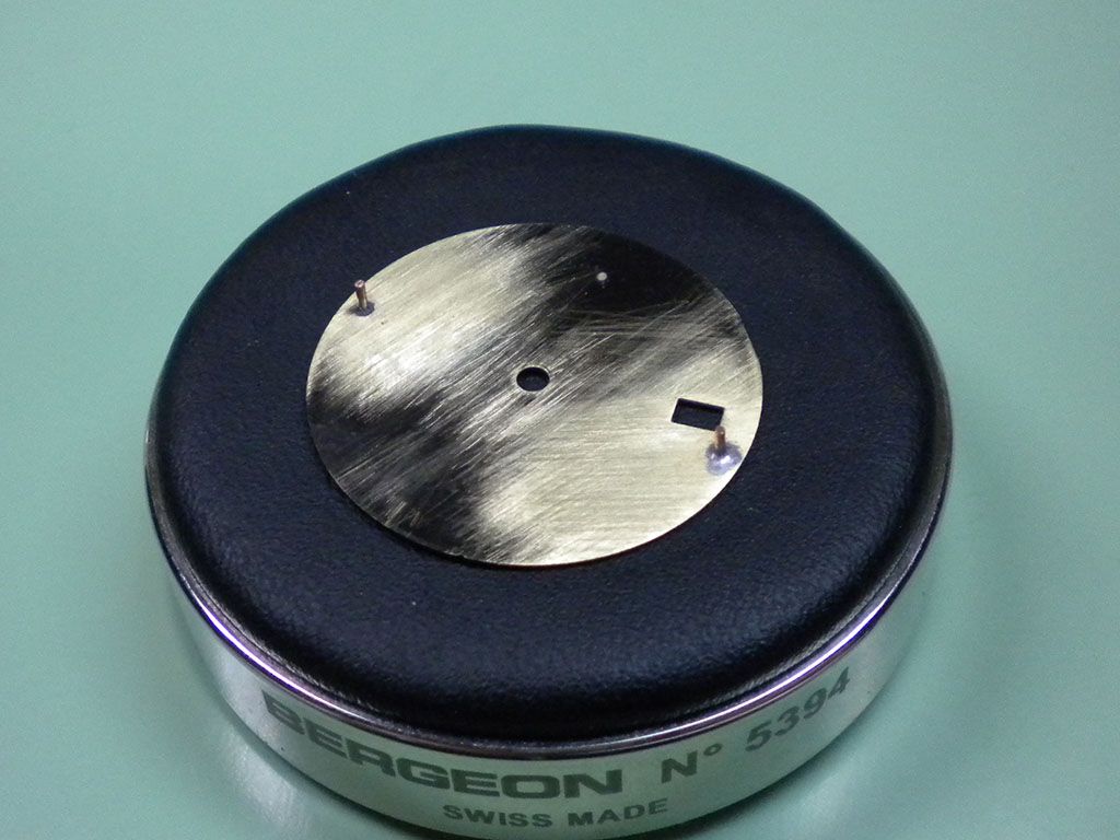
Both cut to length and filed flat.
And most amazingly of all no dial damage. There is a small bit of discolouration by the window where I had my first attempt, but I did have three goes to get that one right thereby putting a lot more heat into that area than would be normal. When I came to attach the second foot I'd refined my method and it only took one attempt to get a strong joint, with the result of no discolouration.
Off to find a few more broken dials for some more practice now.

Wow very cool
Very well done!, seems both you and bob are both working on dial feet at the moment.

Nice job! Will use your tips.

Very interesting and very timely! I'm just about to perform the same thing, though I'll most likely make a mess of it all ...
Any tips about the voltage, amper?
Any reason this can't be done with a "normal" soldering iron (assuming decent temperature regulation and whatnot)?
The soldering iron isn't a soldering iron if you see what I mean, it's just a handy way of holding the carbon rod. It works by holding the carbon rod against the wire near to the joint then applying the current. The heat generated by the carbon arc heats the wire/dial almost instantaniously, it only takes a couple of seconds for the solder to flow. Once the current is stopped it cools down rapidly, hence no scorching of the printed side of the dial. You can see in the pictures where I held the rod as the wire's discoloured and partially melted by the heat generated. If you try heating the joint with a soldering iron it takes too long to get the heat into the dial and it ends up damaging the finish, I tried a few times with various sizes of iron before I gave in and bought the machine.
Last edited by Thewatchbloke; 26th March 2014 at 10:20.
Nice work!
Always best to use the right tools for the job.

I`m impressed! Might have to buy one of these. How much did this fancy new toy cost?
Clearly, there's a risk of marking the printed side of the dial if too much heat goes in; have you tried it on a light-coloured dial to confirm there's no marking?
I`ve fixed dial feet using repair feet (available from AG Thomas) which have a flat base. I`ve secured them with araldite, which is less than ideal. Locating the foot using this method is extremely difficult....not something I`d like to do often.
This method looks like the way to go.
Paul
I got it from these people
http://www.watchlume.com
Although I bought mine on eBay with a best offer.
And here's a link to a video of how it works
http://www.youtube.com/watch?v=bW8foz8E0U8
I practiced on a white, a gold and a beige dial yesterday, no marking at all.
Nice one Dunc, looks great.... Do you want a few old dials to practice on? I'm sure I could rustle up a few...
Cheers..
Jase
I see - very interesting. Definitely agree with others about the right tool for the job, but often it is better to have fewer tools and learn to use them well. Clearly this is one of the exceptions.Originally Posted by Cannop

That's bloomin' neat that is! Great to know there's someone out there who can handle this sort of work.
Thanks for sharing :)
Very nice! What sort of solder do you use?
Best wishes,
Bob
PS This technique of soldering is sometimes known as "resistance soldering".
RLF
I use the recommended type of soft solder Bob, which is of the 60/40 tin/lead rosin core variety. I use 0.7mm diameter (as that's what I already had) and cut it into tiny slices, then cut those slices in half before placing them around the periphery of the joint.
Great stuff,thanks for posting.
Beside laser welding,one more thing for watch repair added to my list.
Really interesting to see this Duncan - thanks for posting. A bit of kit to have in the armory but I'm not sure how often I'd have cause to actually use it!
Martin
Thanks.
Best wishes,
Bob
Here's the method for locating a replacement dial foot that I read about, and use. Get a razor blade and a scribe. Hold the razor blade in the middle of the old dial foot, which I assume has been filed down. Scribe a line. Hold the razor blade perpendicular to the first line and across the middle of the dial foot, and scribe another line. Use the lines to locate the dial foot, i.e., put it so that the lines come out at equal distances from the round bit of the replacement.
My problem in locating dial feet, which I've finally solved (I think), is when I'm doing it for a movement for which I don't have any information, or, even, an old dial.
Best wishes,
Bob
Best wishes,
Bob
Thanks Bob,
My trick with the 'repair feet' (a dial foot attached to a thin flat base) was to trim the base and foot to the correct size, locate the dial foot on the movement, coat with Araldite, then sit the dial on top of the feet and centre it on the hour wheel. This works, but there's potential for the adhesive to go where it shouldn`t. The metal must be clean and scored well, and only the old-fashioned slow-setting Araldite will do. It's stronger than the quick-set variety, which I don`t rate. If all's well, the adhesive hardens, you slacken the screws holding the dial feet, and lift the dial (with new feet) off. Not as good as soldering but far better than adhesive dial pads.
My pet hates are fixing dial feet, and replacing pendant tubes!
Paul
 Posting Permissions