


 Reply With Quote
No specific things to suggest, other than that an oscilloscope might come in handy (although hopefully not).
You may need to desolder components to get good readings. There's a good possibility that one or more of the capacitors is bad (and many people would recommend replacing them all as a matter of course) but PCB tracks, through holes/vias, solder joints, diodes, transistors, resistors and ICs can all fail (so anything really). The biggest difficulty will be if one of the ICs has failed and you can't find a generic replacement, but take it one step at a time. Be systematic, look for continuity where it should be reasonably expected and test components individually where you can. Test continuity working outwards from where the power enters the PCB, a track, joint, via, component at a time.
You mentioned searching for continuity already so I'm very likely saying stuff you already know.
There are some channels on Youtube that specialise in electronic troubleshooting starting off with a multimeter for continuity, resistance and capacitance tests.
Some YT channels:
My Mate VINCE https://www.youtube.com/c/Mymatevince
Adrian's Digital Basement https://www.youtube.com/c/adriansdigitalbasement
Electronics repair school https://www.youtube.com/channel/UCoo...Z0PFAPc4Ymg3RA
CuriousMarc https://www.youtube.com/channel/UC3b...lKYm4sBaLs-Adw (this one is often super-advanced stuff but is nevertheless very informative and educational)
Good luck!
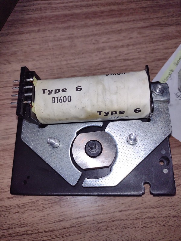
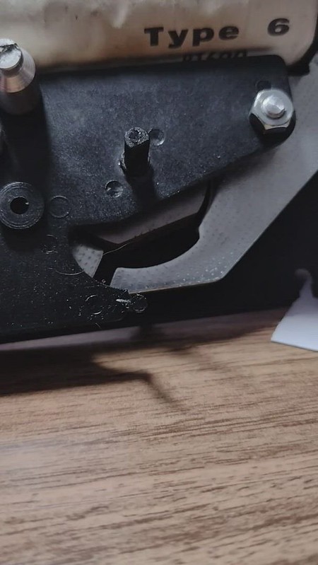
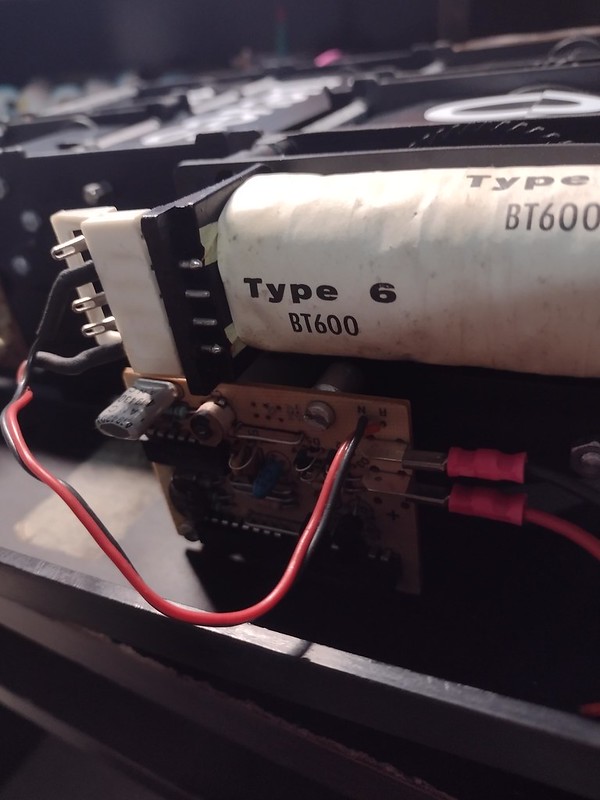
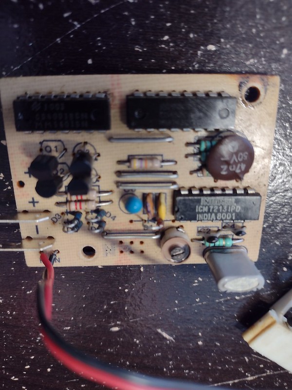
P.S. I was taking a look at the PCB and the components (top down) look to me like:-
Top left and top right: Two ICs. I can't work out the markings well enough to DuckDuckGo them but I reckon they are likely to be some kind of timed pulse generator(s) to flip the display panels when needed. That's just a guess though. (Google/DDG their reference numbers to find their purposes, datasheets, and availability in case faulty).
The four black plastic components labelled Q1, Q2, etc. look like transistors. Check their markings for specs.
To the right of the four transistors is a resistor.
To the right are three more resistors with a capacitor pressed flat on top of them.
Next row down on the left, there are two more resistors and then four diodes directly below them.
The blue spherical thing looks like another capacitor with (I think) two more capacitors to its right, and a diode directly below them.
To the right on this row is an IC, an Intersil ICM7213IPD. This is a timebase generator and its datasheet is available, as is the IC itself. This takes a pulse feed from the crystal and outputs something slower that can be used to tick away seconds, etc. (In this case, I'd like to know what the top two ICs do).
Onto the bottom row now, the cylindrical object with a screw on the top is probably a variable potentiometer or perhaps variable capacitor. I guess/presume that this is used to make timing adjustments.
To the bottom right of the PCB we have another two capacitors and a resistor, and finally the crystal which is the original source for timing.
Suspect all the capacitors. Especially look for faults with the capacitors and consider replacing them all no matter what.